Troubleshooting Permanently Installed AC Accelerometers Powered by a Data Collector
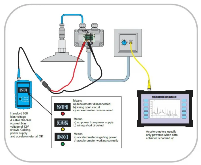
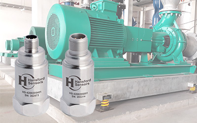
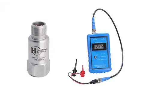
Fig.1 Shows permanently installed accelerometers, powered by a data collector, being measured using a HS-660 cable checker and bias monitor.
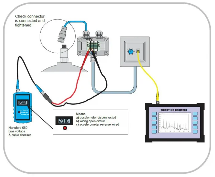
Fig.2 Shows the first troubleshooting step to be taken when the bias voltage is 20V rather than the healthy system bias of 12 VDC.
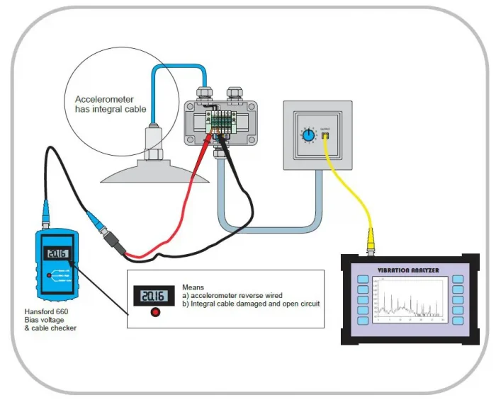
Fig.3 Shows the second troubleshooting step to be taken if it is confirmed that the connector is tightly connected or if the accelerometer is supplied with an integral cable.
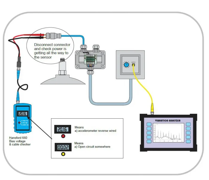
Fig.4 Shows a trouble shooting step if the connector was shown to be tightened correctly. This step confirms or eliminates a cable fault between the junction box and the accelerometer. If the cable is seen to have integrity then the likely fault can be diagnosed as reverse wiring. Very rarely is an open circuit associated with a faulty sensor.
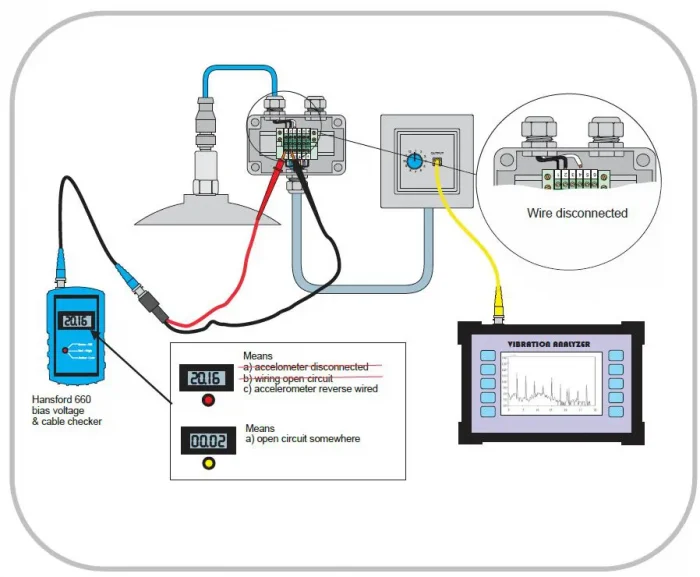
Fig.5 Shows the gradual elimination of possible causes. Here this check can determine loose wires (0V bias) and if the bias checker still shows 20V bias then the likelihood is that the cabling is reverse wired.
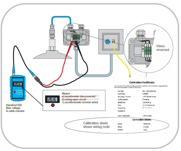
Fig.6 Checking the wiring against the color code on the calibration certificate will show that the likely cause of the 20V bias is reversed wiring.
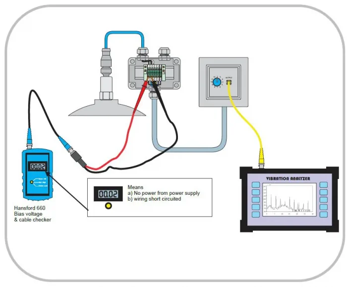
Fig.7 If the bias checker shows 0V then either the power supply to the sensor is not working or that there is a short in the cabling.
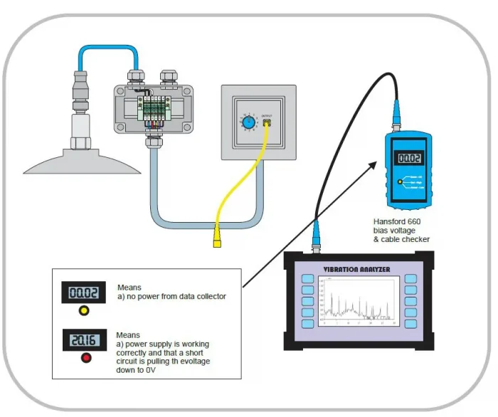
Fig.8 The next step is to verify that the data collector is providing power. 0V in this test would show the data col-lector to be the culprit. If the reading shows 20V then that would confirm that the power is working and is being pulled down to 0V in the other tests by a short circuit in the wiring.
If you have any further questions, please do not hesitate to get in contact with us, or view our product range here.